|
Table of Contents |
Appendix B
BUNKER AND SHELTER ROOF DESIGN
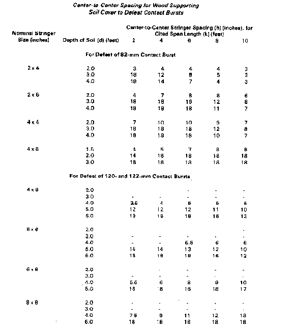
This appendix is used to design a standard stringer roof that will defeat a contact burst projectile when the materials used are not listed in the table, Center-to-Center Spacing for Wood Supporting Soil Cover to Defeat Contact Bursts. For example, if a protective position uses steel and not wood stringers, then the procedure in this appendix is used for the roof design. The table, Center-to-Center Spacing for Wood Supporting Soil Cover to Defeat Contact Bursts, was made using the design steps in this procedure. The calculations are lengthy but basically simple. The two example problems in this appendix were worked with a hand-held calculator and the complete digital display is listed. This listing enables a complete step-by-step following without the slight numerical variation caused by rounding. In reality, rounding each result to three significant digits will not significantly alter the outcome. The roof is designed as follows.
First, hand compute the largest half-buried trinitrotoluene (TNT) charge that the earth-covered roof can safely withstand. Then, use the charge equivalency table to find the approximate size of the super-quick or contact burst round that this half-buried TNT charge equals. The roof design discussed here is for a simple stringer roof of single-ply or laminated sheathing covered with earth (figure B-1). After determining the need for a bunker or shelter roof, the following questions are addressed:
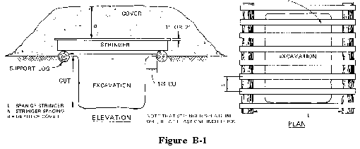
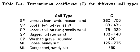
Two soil parameters are needed in the design procedure-unit weight and transmission coefficient. Soil unit weight must be determined at the time and place of design. Both the soil (sand, silt, for example) and its water content affect unit weight. Soil unit weight is usually 80 to 140 pounds per cubic foot. The transmission coefficient can be taken from table B-1
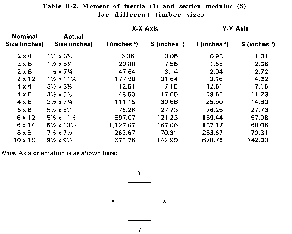
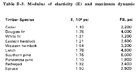
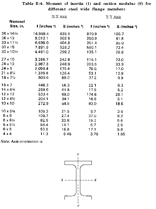
For wood stringers, the data needed in the design procedure are given in table B-2 and B-3. For steel stringers, the moment of inertia (I) and section modulus (S) values needed in the procedure are given in table B-4. For the modulus of elasticity (E) and maximum dynamic flexural stress (FS) values, use E = 29 and FS = 50,000. (Additional structural design data is in FM 5-35.)
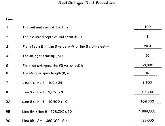
Line
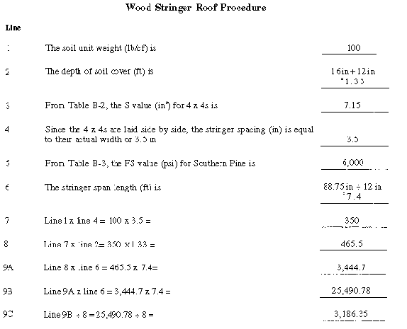
| 1 | Enter the unit weight of the soil (lb/cf) as determined on site | ___________ |
| 2 | Enter the proposed depth of soil cover (ft) | ___________ |
| 3 | Enter the S value (in 3 ): | ___________ |
| if wood, from Table B-2 | ||
| if steel, from Table B-4 | ||
| 4 | Enter the stringer spacing (in) | ___________ |
| 5 | Enter the FS value (psi): | ___________ |
| if wood, from Table B-3 | ||
| if steel, enter 50,000 | ||
| 6 | Enter the stringer span length (ft) | ___________ |
| 7 | Multiply line 1 by line 4, enter result | ___________ |
| 8 | Multiply line 7 by line 2, enter result | ___________ |
| 9A | Multiply line 8 by line 6, enter result | ___________ |
| 9B | Multiply line 9A by line 6, enter result | ___________ |
| 9C | Divide line 9B by 8, enter result | ___________ |
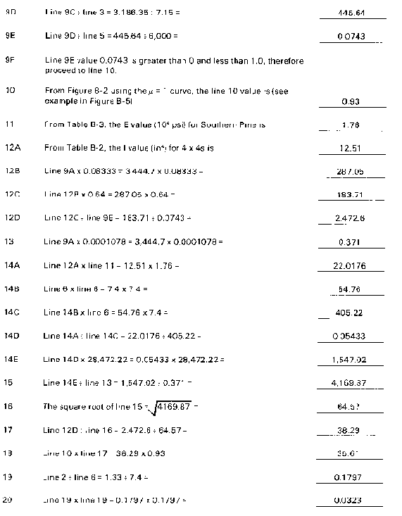
| 9D | Divide line 9C by line 3, enter result | ___________ |
| 9E | Divide line 9D by line 5, enter result | ___________ |
| 9F | If the line 9E result is greater than O but less than 1.0 go to line 10. | ___________ |
| If line 9E is greater than 1.0, the roof system is overloaded. Then do at least one of the following and recompute from line 1: | ||
| a. Decrease stringer spacing. | ||
| b. Decrease span length. | ||
| c. Use a material with a higher "S" or "FS" value. | ||
| d. Decrease soil cover. |
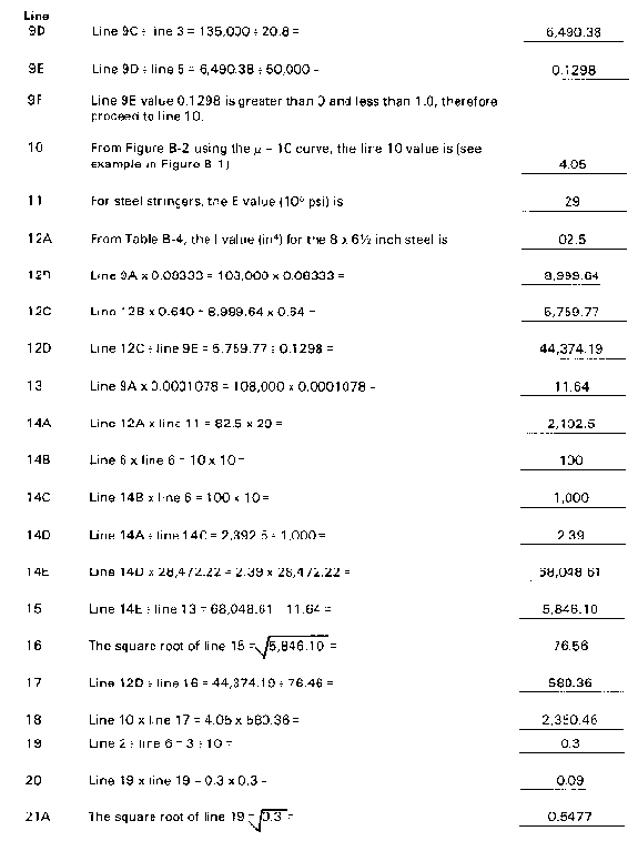
Line
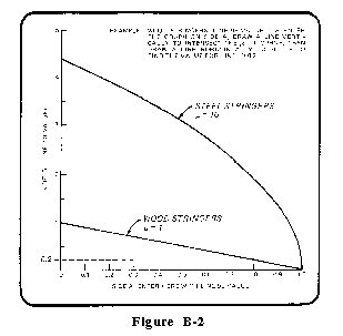
| 10 | Enter side A of Figure B-2 with the line 9E value, find the side B | ___________ |
| value, and enter result: | ||
| if wood, use µ = 1 curve | ||
| if steel, use µ = 10 curve | ||
Line
| 11 | Enter the E value (106 psi): | ____________ |
| if wood, from Table B-3 | ||
| if steel, enter 29 | ||
| 12A | Enter the I value (in4 ): | ____________ |
| if wood, from Table B-2 | ||
| if steel, from Table B-4 | ||
| 12B | Multiply line 9A by 0.08333, enter result | ____________ |
| 12C | Multiply line 12B by 0.64, enter result 1 | ____________ |
| 12D | Divide line 12C by line 9E, enter result | ____________ |
| 13 | Multiply line 9A by 0.0001078, enter result | ____________ |
| 14A | Multiply line 12A by line 11, enter result | ____________ |
| 14B | Multiply line 6 by line 6, enter result | ____________ |
| 14C | Multiply line 14B by line 6, enter result | ____________ |
| 14D | Divide line 14A by line 14C, enter result | ____________ |
| 14E | Multiply line 14D by 28,472.22, enter result | ____________ |
| 15 | Divide line 14E by line 13, enter result | ____________ |
| 16 | Take the square root of line 15, enter result | ____________ |
| 17 | Divide line 12D by line 16, enter result | ____________ |
| 18 | Multiply line 10 by line 17, enter result | ____________ |
| 19 | Divide line 2 by line 6, enter result | ____________ |
| 20 | Multiply line 19 by line 19, enter result | ____________ |
| 21A | Take the square root of line 19, enter result | ____________ |
| 21B | Multiply line 21A by line 20, enter result | ____________ |
| 22 | Divide 0.6666667 by line 21B, enter result | ____________ |
| 23A | Multiply line 20 by 4, enter result | ____________ |
| 23B | Add 1 to line 23A, enter result | ____________ |
| 24 | Divide 4 by line 23B, enter result | ____________ |
| 25A | Take the square root of line 24, enter result | ____________ |
| 25B | Take the square root of line 25A, enter result | ____________ |
| 25C | Multiply line 25B by line 24, enter result | ____________ |
| 26 | Add line 25C to line 22, enter result | ____________ |
| 27 | Choose a C value from Table B-1, enter result | ____________ |
| 28A | Multiply 61.32 by line 18, enter result | ____________ |
| 28B | Take the square root of line 14C, enter result | ____________ |
| 28C | Multiply line 28A by line 28B, enter result | ____________ |
| 28D | Multiply line 27 by line 4, enter result | ____________ |
| 28E | Multiply line 28D by line 26, enter result | ____________ |
| 28F | Divide line 28C by line 28E, enter result | ____________ |
| 29 | Raise line 28F to the 0.8571 power (or use the graph in Figure B-3), enter result | ____________ |
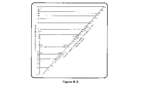
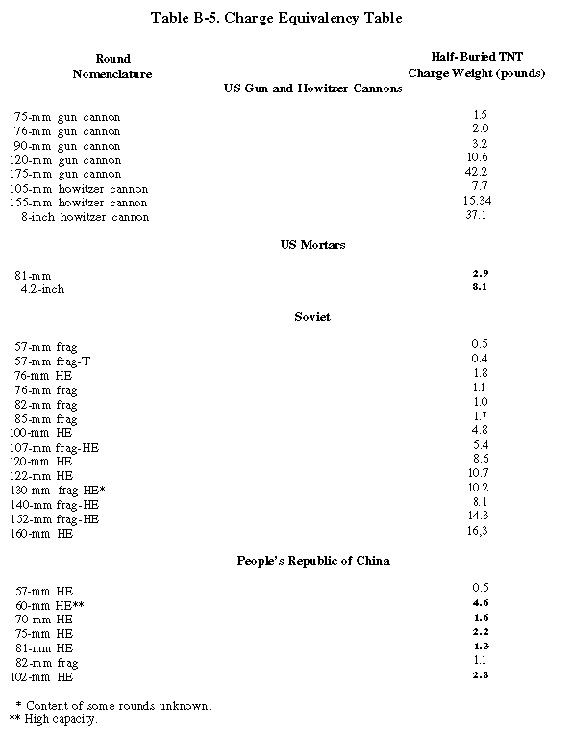
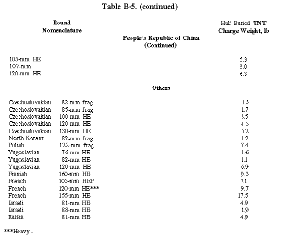
The value on line 29 is the largest half-buried TNT Charge (lb) that the roof can withstand. Enter Table B-5 with this value to find the round having an equivalent charge weight equal to or less than the value on line 26.
The 2-76th Infantry is about to relieve another battalion from defensive positions as shown in figure B-4. The 1st Platoon of the A/52d Engineers is supporting the 2-76th. As its platoon leader, you have been asked to find how much protection such positions give against the contact burst of an HE round.
You first estimate that the 16-inch-deep soil cover (sand) weighs 100 lb/cf. You then note that the roof is made of 4 by 4 stringers, laid side-by-side over a span of 88.75 inches.

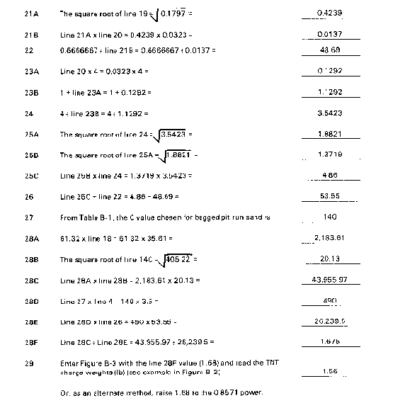
Thus, the largest TNT charge that the roof can withstand is 1.56 pounds. Entering Table B-5 with this value, you find that the roof will withstand a contact burst explosion of up to an 82-mm frag round (only 1.0-pound charge size) excluding the 76-mm HE round (1.8-pound charge site).
The 2-76th Infantry will occupy the positions described in the first example for an extended period of time. Thus, the battalion commander has ordered the 1st Platoon of the A/52d Engineers to construct a tactical operations center. This structure must have at least 10 by 12 feet of floor space and be capable of defeating a contact burst of a Soviet 152-mm round. The S2 of the A/52d Engineers reports that 13 undamaged 8-inch by 6 ½-inch wide flange beams have been found. They are long enough to span 10 feet and can be salvaged from the remains of a nearby demolished railroad bridge.
As platoon leader, you are to design a roof for the tactical operations center using these beams as stringers. You plan to place five of the stringers on 36-inch centers and cover them with a 4 by 4 wood deck. You use the same bagged sand as described in the first example. You begin your design by assuming that the soil cover will be 3 feet deep.
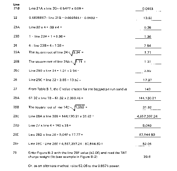
Thus, the largest TNT charge that the stringers can withstand is 29.6 lb. You next use the procedure again in a manner similar to that in example 1 to evaluate the 4x4 wood deck. You find a line 29 value of 29.64. Enter Table B-5 with the largest of these values (29.6), you find that the roof will withstand a contact burst explosion of up to a 160-mm HE round (only 16.3-pound charge size). Thus, the roof you have designed will be capable of defeating a contact burst of a Soviet 152-mm round.